
Or a description as to why accurate wind speed measurements are both essential and unreliable
In our last article in understanding power curve certifications we addressed the many elements that cause their sensitivity to parameters and conditions. Now let's look into NTF and the impact of these wind speed measurements.
Definition:
The nacelle transfer function (NTF) is an attempt to estimate the free stream wind speed using a measurement from the nacelle anemometer (or spinner anemometer, which is mounted in front of the rotor, but that will not be discussed in this presentation). Said another way, what is the wind speed unaffected by the turbine’s moving parts.
The measurement at the nacelle anemometer is not an accurate representation of the free stream wind speed and direction because the wind flow (both speed and direction) is affected by
- The shape of the nacelle, hub spinner, blade roots and blades
- The rotation of the blades
- The energy conversion from wind power to electrical power by the turbine
- Anemometer measurement uncertainties
- Anemometer calibration inaccuracies
- Measurement at hub height only
The raw measured wind speed could be larger or smaller than the true free stream wind speed. Therefore, changes in NTF can affect controller behavior, performance metrics and power estimates. Or said differently, accurate wind speed measurements are both essential and unreliable.
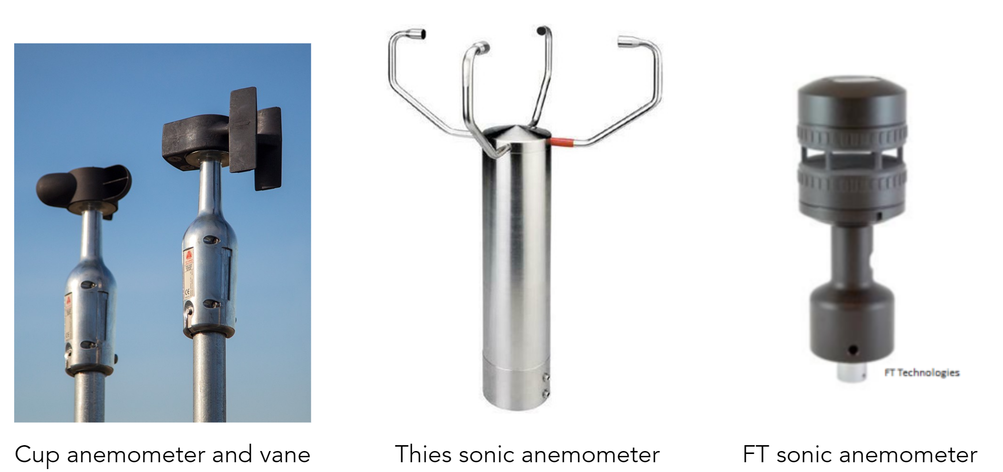
Sonic anemometers can measure both wind speed and direction, but a mechanical cup anemometer only measures wind speed, so a vane is needed to measure wind direction
Calculating the wind speed
The conversion from a measured wind speed at the anemometer to an estimate of the free stream wind speed typically requires several steps
- First, the anemometer will generate an electrical signal that must be converted to a measured wind speed (this is typically determined by an instrument calibration)
- Next, this measured wind speed signal needs to be converted to an estimated free stream wind speed (this is typically determined either experimentally or theoretically)
Ideally, each of these transformations would be tuned for each individual anemometer/turbine combination on a farm. More generally, these transformations are done uniformly for a given anemometer/turbine combination.
Typical nacelle transfer functions may be:
- Scalar
- Linear
- Quadratic
- Table lookup
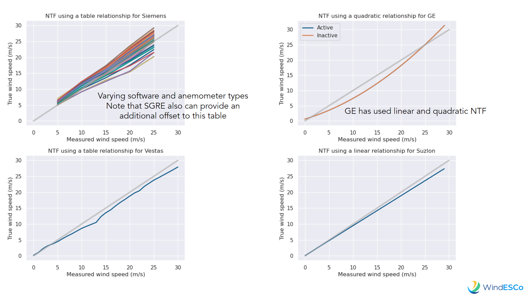
Translating nacelle wind measurement is complicated, and often inaccurate because the same NTF may be used across multiple turbine locations and farms.
For example, four major OEMs all have different approaches to NTF:
IEC 61400-12-2 Edition 1, 2013-03 defines how the nacelle anemometer may be used to certify a power curve. These general principles will be presented here as an ideal determination of a nacelle transfer function
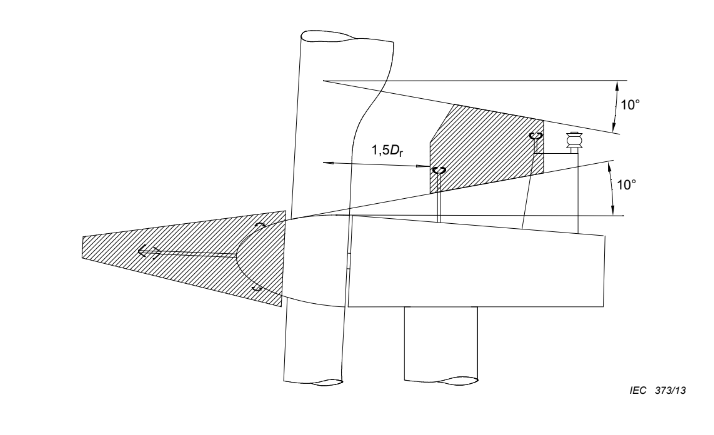
Nacelle anemometer location
The anemometer location on the nacelle is explicitly defined by the standard
- Above nacelle boundary layer (10°)
- Below cylindrical root to shaped blade transition
- Upwind of other sensors or lights
- More than 1 meter in from of downwind end of nacelle
- 1.5 root diameters (Dr) from blade root center
- Spinner anemometer must be 0.6Dr in front
Power curve certification with nacelle anemometry
There are several similarities and differences with nacelle anemometer certification and the previously discussed power curve certification
Similarities:
- Sector qualification by 10 deg wind directions
- Fill wind speed bins
Differences:
- Generate NTF using relationship between a met mast (or LiDAR) and nacelle anemometer
- Confirm uniformity of NTF for all directions
- Fit linear equation or create a table for NTF
- No extrapolation of NTF is allowed - need to fill all bins (met wind as function of nacelle)
- Can generate an NTF per direction
After NTF is generated, repeat binning process with power
- AEP/Power can vary no more than 1% of bin power or 0.5% of rated power, whichever is larger
- OEMs may use this NTF at other farms for same turbine model
Determining the NTF
There are two main uncertainties in calculating the NTF: yaw angle and wind direction measurement. To manage this are two strategies OEMs:
- Use a valid measurement sector as discussed previously in the certification process resulting in,
- Potentially invalid measurements
- Vertical flow inclination angle too high, and/or sectors with steep slopes
- Obstacle influence is more complex than anticipated
- Or, they use a self-consistency check to provide a second validation
- Create a reverse power curve (wind speed as a function of power) from valid measured data
- Interpolate wind speed from measured power for all directions, using this reverse power
- Compare NTF measured wind speed to interpolated value - if close to 1, then sector is valid
- Waked turbines will have different wind speed measurements with respect to power
OEMs with self-calibrating NTF claim to use measured power to correct wind speed back to the power curve. However, WindESCo has concerns about this approach given the NTF may be compensating for degradation in performance. In other words, data may be off of curve because performance is poor.
This means NTFs can’t be trusted, but what else are you going to? It is best to avoid using wind speed measurements to assess turbine performance as much as possible because it is easier to move a power curve left than it is to move it up. As such, keep in mind our next topic, rotor equivalent wind speed (REWS)!