
Identifying and understanding WindESCo's yaw misalignment
What is yaw misalignment?
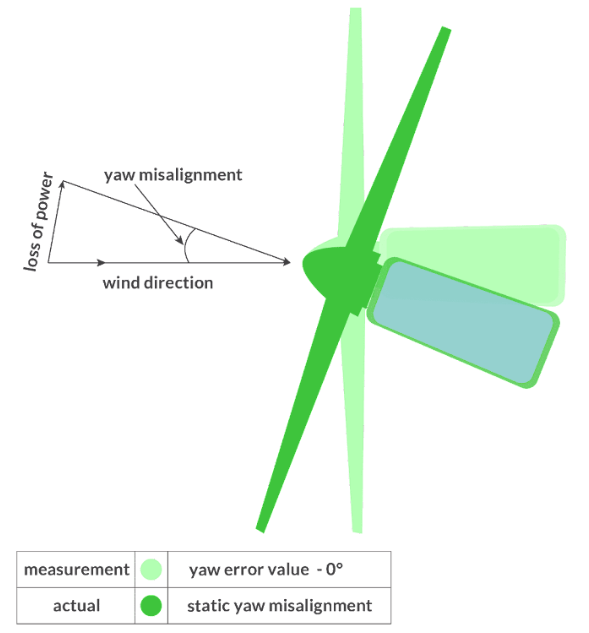
- Static yaw misalignment occurs when measured yaw error is 0°, but the turbine is not pointing directly into the wind.
- The turbine cannot see the difference between measurement and reality, making the misalignment invisible to the turbine controller.
- This type of misalignment reduces AEP and increases lifetime consumption.
Can you see this in 10-min data?
- It is difficult to detect turbine problems using power curves. Two power curves can appear similar, even when one has significant yaw misalignment
- For example, below is the power curve of two turbines. The power curves are similar, but one has significant yaw misalignment (6° Yaw Misalignment detected on turbine ID :1580)
- Impact of this misalignment was: 1.1% AEP for turbine, 0.6% AEP for the farm
- Once corrected, this resulted in an increase of $4,300/Yr for turbine, and $320,000/Yr for farm
- Yaw misalignment is best detected using a smaller scale than the 10-minute data typically used in power curves.

How do you identify this issue?
- We model the relationship between wind characteristics and turbine behavior using data sampled at high frequency, then use this relationship to determine the optimum static yaw error offset.
- Our algorithm combines machine learning with a physics-based methodology to provide ongoing estimates of the static yaw misalignment, which often changes over time.
- This approach has been validated through experiments and field deployment
- AEP improvements have been observed on multiple turbine models at various geographical locations.
- Our approach is to track the optimal alignment on a turbine-by-turbine basis so this is not a generalized approach applied to the farm
- In sum, we do a high-speed analysis on the turbine parameters and signals to determine the ideal offset to provide maximum power from the turbine (acknowledging that this may be slightly off a direct perpendicular to the wind flow)
- As alluded above, our algorithm has been developed over many years and has successfully been applied to ~1500 turbines to date with a DNV approved Energy Improvement Assessment after the fact to ensure the AEP gains are measurable
How are the AEP gains calculated? What data set is used to track the gains?
There is a loss model for each issue/turbine. A loss model is an algorithm used to estimate the energy that is being lost, or alternatively, that could be gained by optimizing the operating conditions of a wind turbine. The specific loss model for each issue is chosen by our subject matter experts based on their extensive experience in wind energy, physics and engineering-based principles, the latest industry techniques, current academic research, and customer feedback.
To calculate the losses for a given issue, WindESCo leverages loss model calculations specific to the issue and actual wind and turbine measurements to ensure that an accurate estimation is provided. For example, static yaw misalignment has a loss model that uses a cos-squared relationship for the Region 2 power loss. More specifically, the cosine squared of the yaw misalignment is multiplied by the power of all the timestamps where the turbine is in region 2 of the power curve during a certain time period.
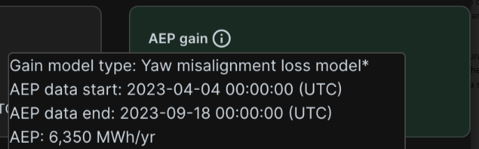
For example you can see the time period/data set used by hovering over the info icon on the gains card where you can see the AEP data timestamps.
When an issue is fixed, the gains are tracked through an inverse of the loss model, that is, what the losses would have been if the issue were not corrected during the period of 1 year. Since this farm has less than a year of data, we extrapolate very simply based on the missing data fraction, i.e., if the data covers 0.4 of a year, we divide the annual energy gain by 0.4 (the percent gain is unchanged though since that would be redundant). This is determined from the number of 10 minute samples present divided by the total number of expected 10 minute samples in the year, so it will account for data gaps. See the full article explaining this approach here
How do you track and confirm this issue is corrected?
To ensure that gains are not tracked when a Fix is incorrectly applied, WindESCo continues to review all issues on a continuous basis. Any issue that is re-identified will then have its gains appropriately adjusted to reflect that the issue was not properly addressed. With further data ingestion we will see if the misalignment was indeed properly fixed. This is how you will be able to see that you correctly resolved the static yaw misalignment issue:
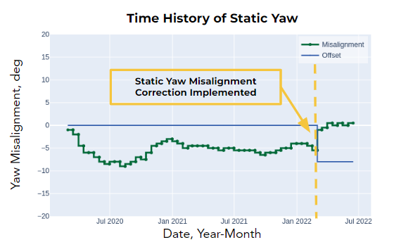
- WindESCo can track the yaw misalignment correction over time
- Typically a confirmation of correction is observable within 4-6 weeks and a full EIA can be completed once 3 months have passed
Common Questions:
- Load impact of yaw misalignment correction:
- The IEC turbine design standard, load on turbines is typically modeled with ⅓ of the total lifetime at respectively -10°, 0° and +10° (some manufacturers use 8°) static yaw misalignment
- This is not a transient analysis, but a sustained 1/3 lifetime at 10, 1/3 at -10 and 1/3 at 0 degrees
- Therefore a change of less than ten degrees is not a risk to any component if the turbine has been designed per the IEC standards
- Comparison to Lidar:
- There are a few technical concerns we have with using ground-based lidar for determining static yaw misalignment, which we believe will result in misleading and incorrect yaw error estimates. Our technical team has previously explored the viability of ground-based systems for yaw misalignment detection and the uncertainties in the results motivated our team to pursue the data-driven approach we currently employ. Some of the technical issues related to using ground-based lidar for yaw misalignment include:
- Foremost, lidar leveling and calibration relative to true north (i.e. north-based alignment) are difficult. Any error in this calibration will enhance statistical uncertainty in the yaw error estimates.
- It is difficult to temporally align the two systems (lidar and turbine) relative to one another. Even after initial temporal alignment, time measurements in one system can drift relative to the other leading to temporal inconsistencies between the two datasets.
- Depending on the ground-based lidar and the scanning strategies employed, it will take an extended amount of time to extract a single wind profile estimate. Based on this measurement time interval, the wind profile extracted will be a spatiotemporal average of the wind conditions over that interval. Therefore, a direct comparison between the derived wind profile and operational turbine data is not optimal. The measurement time will also impact the number of samples that can be collected in a given time period (this is not true for a data-driven approach). Given the same time period, a data-driven approach will provide a significantly higher number of comparison points for evaluating static yaw misalignment.
- The ground-based lidar will need to be situated some distance away from the turbine so it remains outside the induction zone of the turbine; in the induction zone wind conditions can be modified by both the physical and operational presence of the turbine. Because of this there will inherently be a temporal lag between the time of measurement and when the measured wind conditions interact with the turbine. Furthermore, any spatial variability in the wind conditions will need to be assumed insignificant. Finally, there will be a limited number of valid wind direction sectors that can be used for evaluating static yaw misalignment due to potential waking.
- With a ground-based system, assumptions will need to be made as to how to correlate the rotor-relative wind direction conditions (i.e. wind veer across the vertical depth of the wind turbine rotor sweep) with the nacelle orientation of the turbine to determine yaw error.
To learn more, you can also check out our: