
Detailing the methodology and approach of the rotor imbalance check
Description of the check:
A turbine shows significant rotor imbalance compared to peers. The imbalance may be caused by unevenly distributed mass or unequal blade aerodynamic performance between blades, e.g., from pitch misalignment. Excessive rotor imbalance may cause structural vibration and thus affects component reliability and energy loss if shutdown events are triggered.
Introduction:
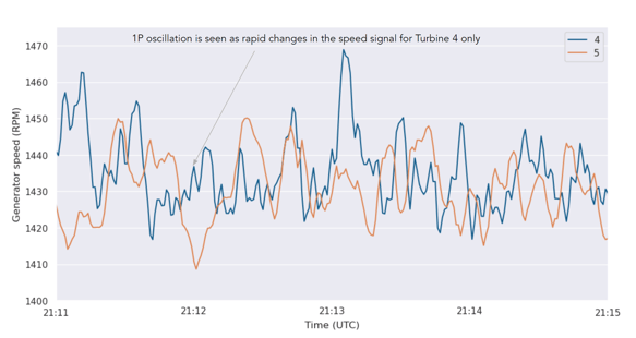
Rotor imbalance may be observed in the rotor or generator speed signal at the 1P frequency when the sampling rate is greater than twice 1P- For a 15 RPM rotor speed (0.25 Hz), a 2 second sample rate is the minimum viable rate
- At slower rotor speeds, more samples are available per revolution
- When 1 second data is available, it is possible to detect rotor imbalance
- The two articles provided in the bibliography have more details on this approach
- This check will only identify the presence of rotor imbalance
- Does not currently determine whether it is mass or aerodynamic imbalance
- Does not determine which blade or blades is out of balance
- This check does identify which turbines require further review to confirm the affected blades
- Work is ongoing to determine a method to separate aero and mass imbalance as well as identify the blades that are imbalanced
Rotor Mass Imbalance:

The figure to the right shows a typical modeling of a rotor mass imbalance, in which there is a modeled additional mass, m, located at a distance r and an angle 𝜑m from blade 1. This represents the average mass imbalance across all blades.
This mass imbalance creates an additional torque whose magnitude varies during a blade rotation
Mass imbalance also induces a centripetal force which increases the loads on the turbine and may be observed through vibration monitoring as well as through the rotor speed signal.
Aerodynamic Imbalance:
Aerodynamic imbalance is a more complicated imbalance source:- Occurs both at 1P and at 3P ± 1P (i.e. 2P and 4P)
- These sidebands around 3P are used to distinguish aero from mass imbalance
- The aerodynamic imbalance magnitude will also vary with the wind speed, so its contribution is larger at higher wind speeds, and therefore, for a constant tip speed ratio, at higher RPM
- See the Shahriar article (reference at end) for more details
Interpretations of 1P magnitude:
For a 1 second sampling rate:
- In a case with both mass and aerodynamic imbalance, it would be expected that the magnitude of the 1P component is larger than nominal at RPM, but it increases quadratically with increasing RPM
- A positive result in this case would require further investigation and review of vibration measurements to confirm the imbalances
For faster than 1 second sampling rates (> 1 Hz):
- It may be possible to identify the 2P characteristic of aerodynamic imbalance to provide a more accurate determination of the separation between the two types of imbalance
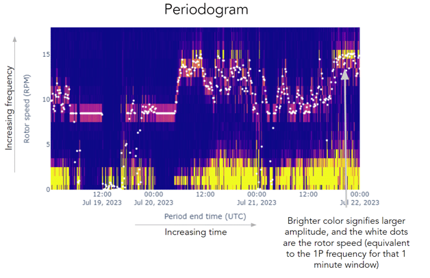
Periodogram spectral analysis:
To identify large 1P signals, WindESCo performs a periodogram (or spectrogram) analysis
For each turbine:
- 1 minute windows of the rotor speed signal are analyzed
- The 1 minute average rotor speed is used to identify the 1P frequency
- 1P = 1 minute average rotor speed / 60
- The magnitude of the 1P frequency is recorded for each 1 minute window
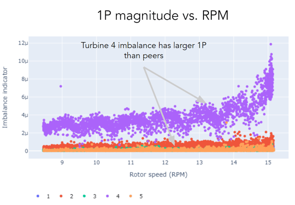
- These magnitudes are compared to all other turbines at the farm at all rotor speeds
- Turbines with higher 1P magnitudes than their peers are identified as having a rotor imbalance
- This peer comparison currently assumes the same rotor and blade types
WindESCo provides two key pieces of evidence - the periodogram and the 1P magnitudes vs. rotor speed for all reference turbines
Conclusions:
The WindESCo rotor imbalance detection identifies turbines with larger 1P components of the rotor speed signal, relative to peer turbines
- This method does not identify the magnitude of the 1P
- This method does not identify the affected blades
- This method does not separate the aerodynamic and mass imbalance effects
Further investigation is required with vibrational analysis to determine affected blades and magnitude of the mass and aerodynamic imbalance
WindESCo is working to identify a method to conduct a SCADA-based experiment to help isolate the affected blades
References:
Niebsch, Jenny & Ramlau, Ronny & Nguyen, Thien. (2010). Mass and Aerodynamic Imbalance Estimates of Wind Turbines. Energies. 3. 10.3390/en3040696.
Shahriar, Md. Rifat & Borghesani, P. & Tan, Andy. (2015). Speed-based diagnostics of aerodynamic and mass imbalance in large wind turbines. 10.1109/AIM.2015.7222635.